














English
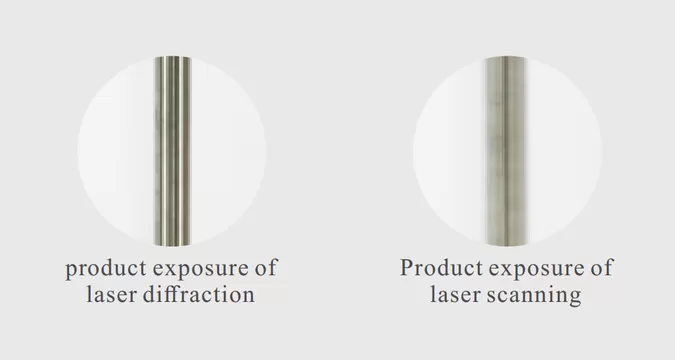
Extremely short exposure time, capable of capturing object images without any blur or shadow, ensuring accurate measurement.
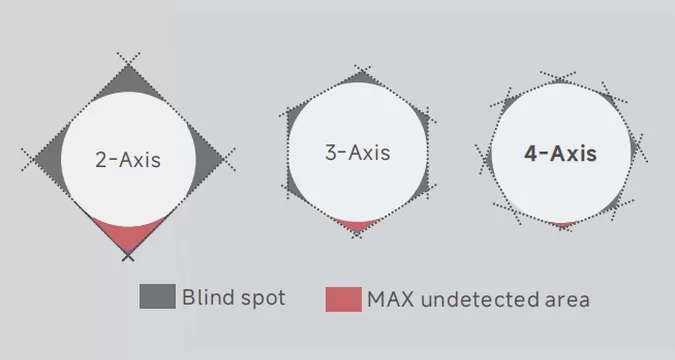
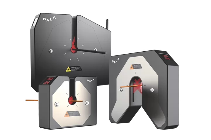
The figure explains the relationship between the measurement result and the number of axes. The more axes there are, the smaller the blind area becomes, resulting in more accurate measurements.
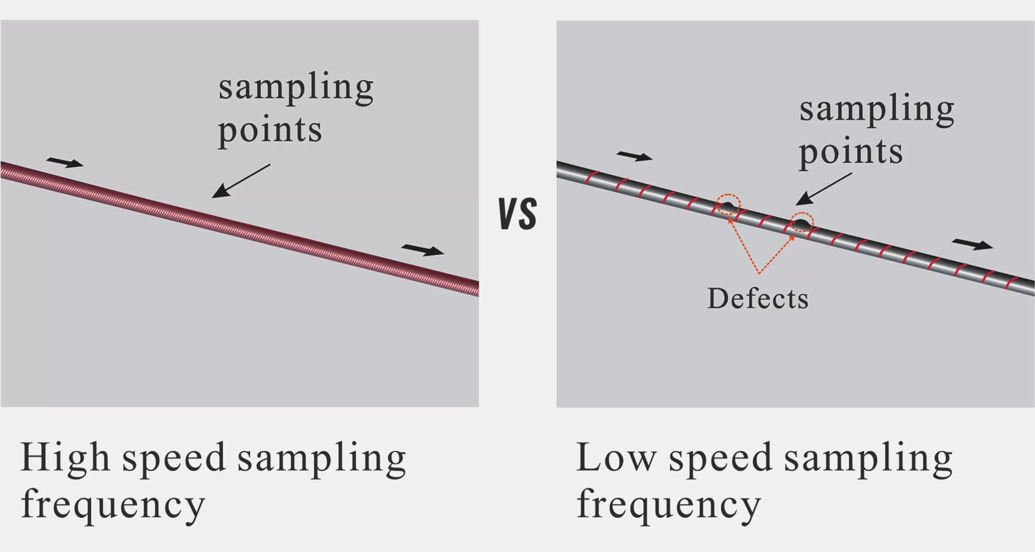
Sampling frequency can reach up to 10kHz due to no motor running speed limitation, which enables getting more information about the object under measurement.
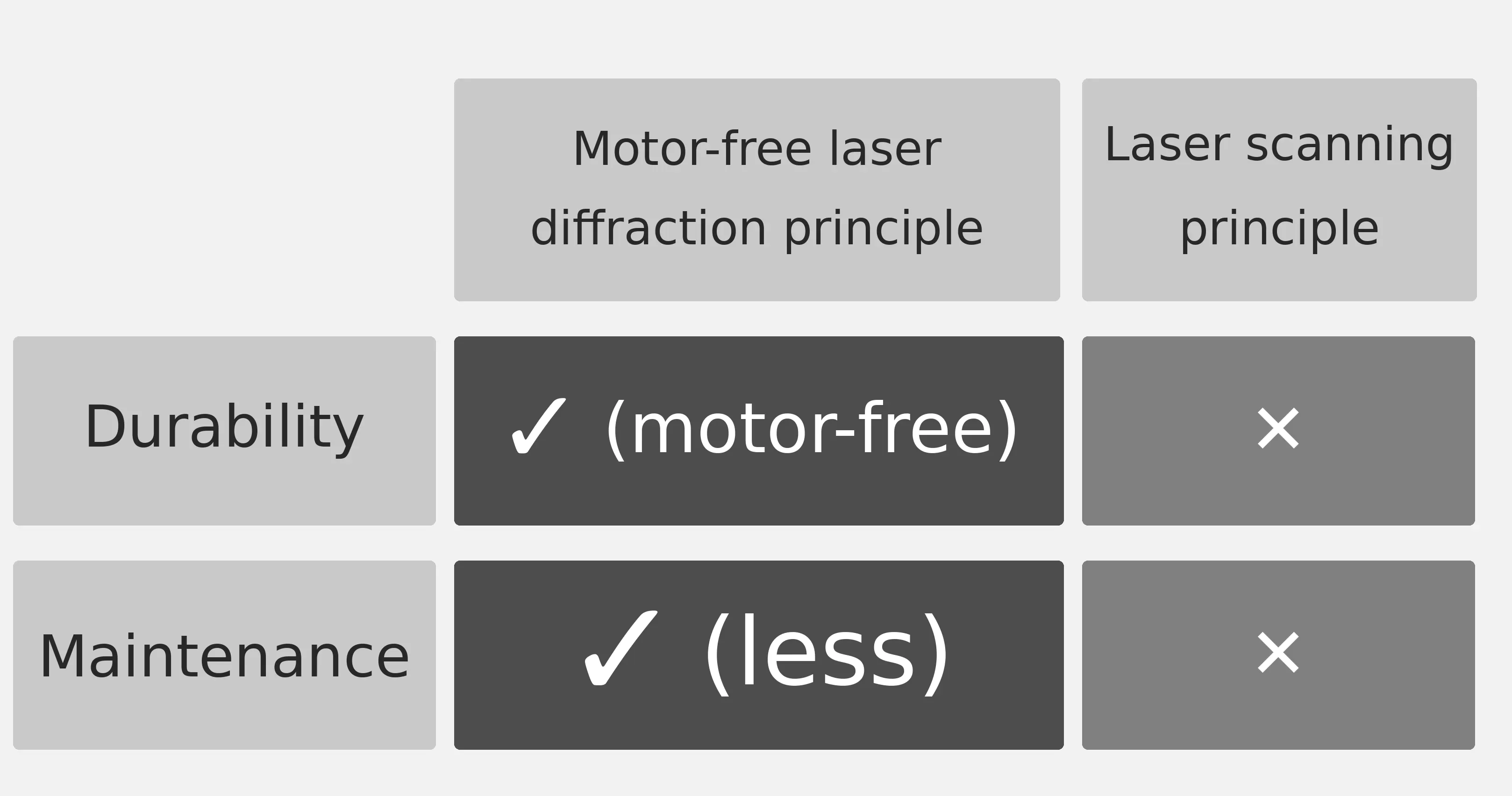
Thanks to no moving parts inside, there is no measurement deviation caused by long-term use.
| Model | F2010-S | F2030-S | F2010-K | F2030-K | F4010-K |
| Axis | 2 axis | 2 axis | 2 axis | 2 axis | 4 axis |
| Measurement data | diameter & ovality | diameter & ovality | diameter、ovality、lump & necks | diameter、ovality、lump & necks | diameter、ovality、lump & necks |
| Frequency | 1000Hz | 1000Hz | 10KHz | 5KHz | 10KHz |
| Measurement range | 0.2~10mm | 0.5~30mm | 0.2~10mm | 0.5~30mm | 0.3~10mm |
| Repeatability | ±0.1μm(1) | ±0.2μm(2) | ±0.1μm(3) | ±0.2μm(3) | ±0.2μm(3) |
| Accuracy | ±(0.0005+0.01%*D)mm(1) | ±(0.001+0.01%*D)mm(4) | ±(0.0005+0.01%*D)mm(3) | ±(0.001+0.01%*D)mm(4) | Diameter accuracy(mm) ±(0.001+0.01%*D)(3) Ovality accuracy(mm) <0.5mm: ±0.004 ≥0.5mm: ±2*(0.001+0.01%*D) |
| Min defect height | N/A | N/A | 0.01mm | 0.01mm | 0.01mm |
| Min defect length(5) | N/A | N/A | 0.2mm@120m/min 0.5mm@300m/min |
0.2mm@60m/min 0.5mm@150m/min |
0.2mm@120m/min 0.5mm@300m/min |
| Size | 155x140x58mm | 280x245x58mm | 155x140x58mm | 280x245x58mm | 275x242x60mm |
| Power supply | 24VDC ±5% ,Max.42W | 24VDC ±5% ,Max.46W | 24VDC ±5% ,Max.42W | 24VDC ±5% ,Max.46W | 24VDC ±5% ,Max.46W |
| Working temperature | 5~50 ℃ | ||||
| Display | LED display | ||||
| Communication port | Standard: RS485 MODBUS RTU Option: PROFIBUS、PROFINET、EtherNet/IP、EtherCAT(6) |
||||
| Electrical port | Standard: digital output(relay),digital input,encoder pulse input port Option:PI feedback control(6) |
||||
| Data collection & analysis | Options: TDC 3000, DMS1000, C3, DSI4ZT | ||||
| Out-of-tolerance alarm | Available | ||||
| Transparent mode | Available | ||||
Note:
(1)Set average time to 0.1s and measure the ±2σvalue of the φ1mm round rod at the measurement area center;
(2)Set average time to 0.1s and measure the ±2σvalue of the φ10mm round rod at the measurement area center;
(3)Move φ1mm round rod in the measurement area and conduct measurement error;
(4)Move φ10mm round rod in the measurement area and conduct measurement error;
(5)set defect measurement average time as 0ms, the minimum arc defect length which cannot be missed at the measurable area;
(6)Industrial communication module and PI feedback control module is installed before ex-factory,so notify the demand before placing an order.
Technical documents such as product manuals, datasheets and outline drawings
Answers to frequently asked questions about Laser Micrometer
Yes. Several DALA models support both outer diameter and ovality measurement, including the E3 ultra-fine wire gauge, F Series, TL-2000 Series, and TL-3000 Series.
Yes. DALA diameter gauges can measure 3D printing filaments in different colors.
Yes. It can be integrated with the extruder through PI control, with adjustment signals output via analog signals or communication interfaces.
Used together with Laser Micrometer to build a complete measurement solution
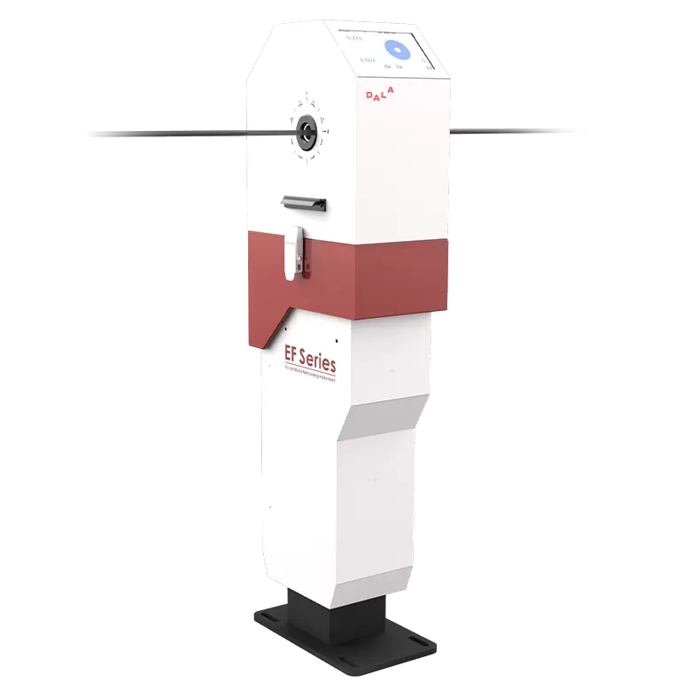
Provides end-to-end support from product selection to production line operation through on-site guidance and after-sales technical support.