













English
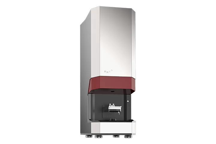
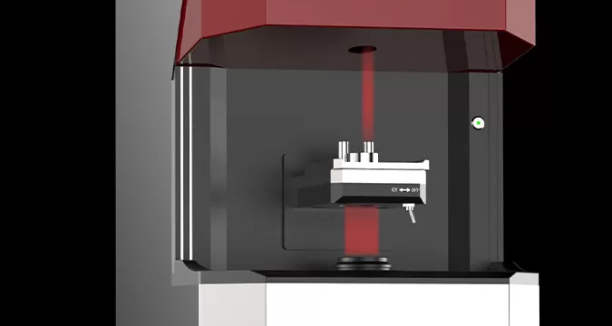
It adopts USB 3.0 high-speed data transmission channel, efficient software algorithm and large working-area optical system to realize real-time measurement of inner hole diameter and ovality. During operation, users do not need to click the mouse or wait. No focusing is required for measurement. After placing the die, readings can be obtained directly for accurate results.
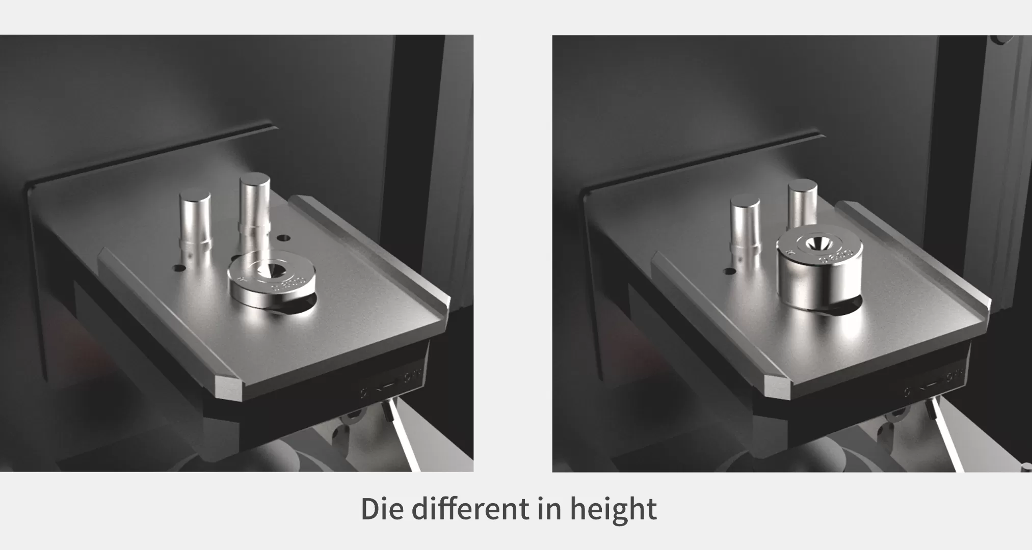
The proprietary optical system delivers sharp and clear edge imaging of the measured object. Combined with dedicated software algorithms, the measurement results remain consistently accurate even when the die is flipped, rotated or repositioned repeatedly. Benefiting from the ultra-long longitudinal working range of the optical system and spatial compensation algorithm of the software system, accurate measurement can be performed when the die sizing zone is at different height levels. Measurement results are not affected by die height or outer sleeve size.
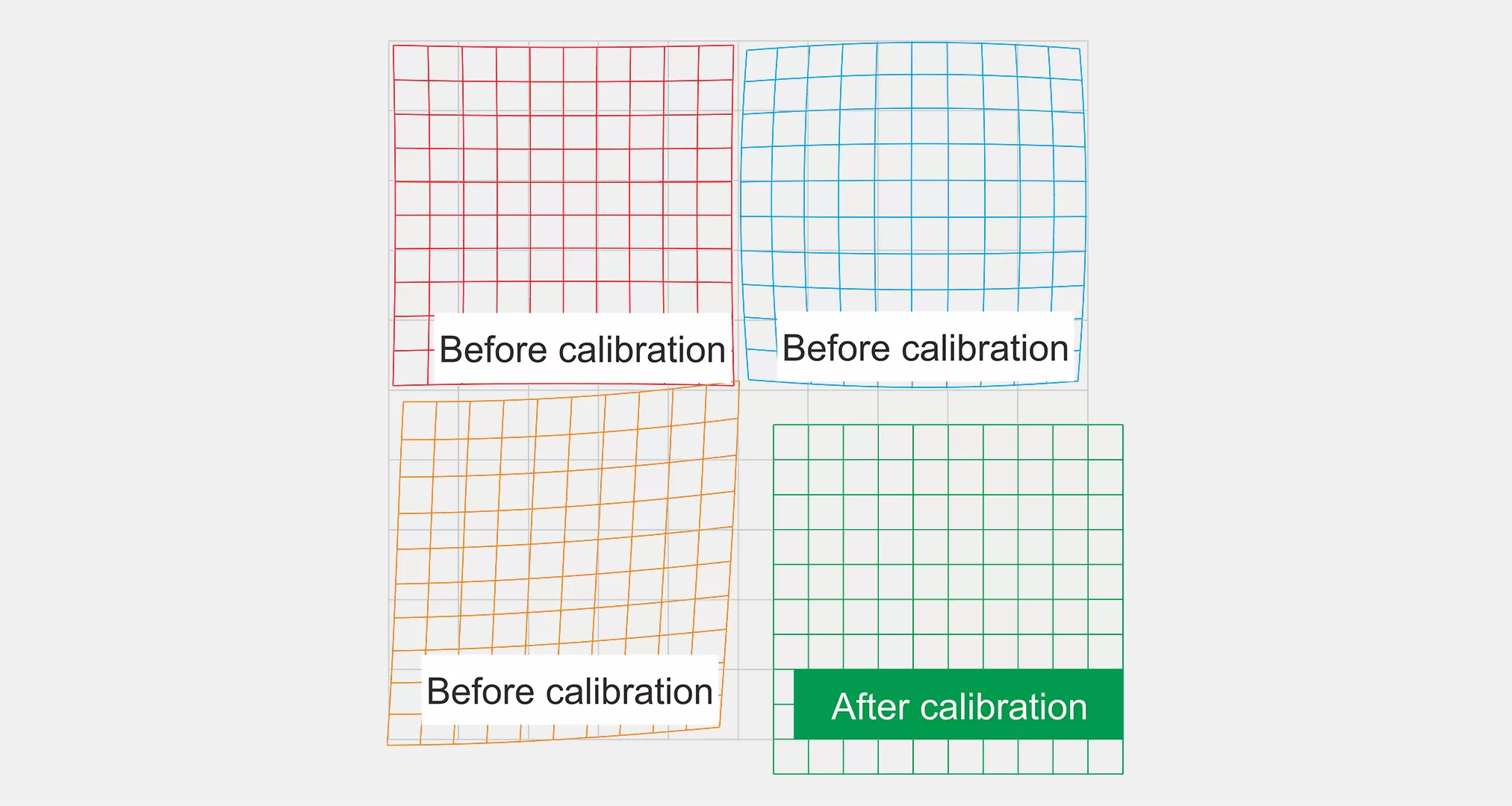
Conventional optical systems suffer from severe lens distortion, leading to inconsistent measurement results when the die is placed at different positions within the measuring area. Every lens adopted by the DM100 undergoes precise calibration. The measurement results meet accuracy specifications regardless of the die’s position on the screen.
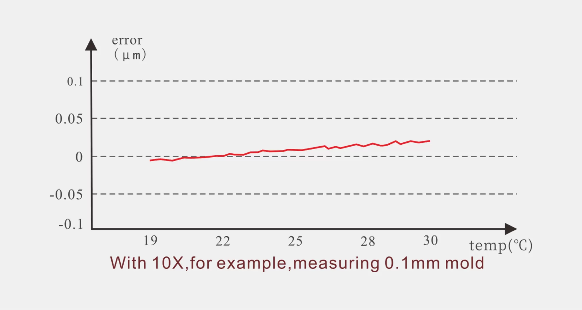
Each unit is equipped with multiple reinforcement structures inside. All fasteners are treated with a special process to increase hardness, keeping the optical system structure long-term stable and ensuring measurement accuracy.
| Objectives | Parameters | ||||||
| Lens Magnification / Measuring Range / Accuracy(1) | 10X | 0.035-0.450 mm | ±0.0006 mm | ||||
| 3X | 0.110-1.500 mm | ±0.0009 mm | |||||
| 1X | 0.350-4.500 mm | ±0.0012 mm | |||||
| 0.5X | 0.700-9.000 mm | ±0.0024 mm | |||||
| 0.25X | 1.000-20.00 mm | ±0.0050 mm | |||||
| 0.1X | 4.000-45.00 mm | ±0.0100 mm | |||||
| Lens Magnification | 20X | 10X | 3X | 1X | 0.5X | 0.25X(2) | 0.1X(2) |
|
|
70 mm | 160 mm | |||||
|
|
32 mm | 75 mm | |||||
|
|
0.5kg | 10kg | |||||
| Report print | Diameter and ovality | ||||||
| Storage and export | Max. save 20,000 copies, export in MS Excel or TXT | ||||||
| Calibration | YES | ||||||
| Software upgrade | YES | ||||||
| Power supply | 24 VDC ± 5%, Max. 36W | ||||||
| Data interface | USB3.0 (compatible with USB2.0) | ||||||
| Operating system | Windows10 or Above | ||||||
| Operating environment | Relative humidity 15~80%, temperature +15°C~+30°C, Noise <70dB | ||||||
| Storage environment | Relative humidity 8~80%, temperature 0°C~+50°C | ||||||
| Gross Weight | 30kg | ||||||
| Size | 300D x 270W x 735H(mm) | ||||||
| Notes: (1) Repeatability is generally 3 to 5 times better than accuracy; (2) 0.25X and 0.1X are only applicable to DM100. |
|||||||
Technical documents such as product manuals, datasheets and outline drawings
Answers to frequently asked questions about 2D Die Aperture Gauge(DM Series)
|
Lens Magnification |
2D Measurement Range (mm) |
3D Measurement Range (mm) |
|
20X |
0.015-0.200 |
0.020-0.035 |
|
10X |
0.035 - 0.450 |
0.035 - 0.110 |
|
3X |
0.110 - 1.50 |
0.110 - 1.000 |
|
1X |
0.350 - 5.00 |
0.400 - 4.000 |
|
0.5X |
0.700 - 9.00 |
0.800 -8.500 |
|
0.25X |
1.00-20.00 |
2.00-20.00 |
|
0.1X |
4.00-45.00 |
4.00-45.00 |
Switch to a lower-magnification lens. For example, if you are using a 10× lens, switch to 3×.
Move the die stage and look for a bright spot in the software image. Once found, move the bright spot to the center of the image, then adjust the Z-axis until the double-ring image becomes clear.
Switch back to the original magnification. Move the die stage again to center the bright spot, then adjust the Z-axis until the double-ring image is clear. If the image is already clear after switching back, no further Z-axis adjustment is needed.
Ar(%) is an input parameter used to calculate the bearing length.
Ar1(%) and Ar2(%) are input parameters used to calculate the reduction angle. Their positions in the measurement interface are shown below:
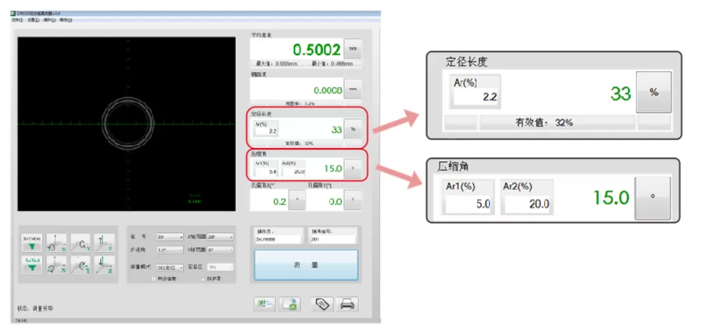
In the example above, Ar(%) = 2.2. This means the bearing length is calculated based on the position where the die bore cross-sectional area reaches (1 + 2.2%) × A, where A is the minimum cross-sectional area of the die bore.
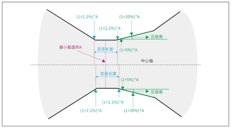
Starting from the minimum area A (purple dashed line below), the area increases by 2.2%, creating two positions as indicated by the blue arrows. The calculated bearing length in this example is 33%.
Ar1(%) = 5.0 and Ar2(%) = 20.0. The reduction angle is calculated using the positions where the die bore cross-sectional area reaches (1 + 5.0%) × A and (1 + 20.0%) × A.
Starting from the minimum area A (purple dashed line below), the area increases by 5% and 20%, creating two positions shown by the green arrows. The calculated reduction angle in this example is 15°.
Note: The die bore cross-sectional area is calculated from the radius along the die center axis, so two bearing length values and two reduction angle values can be obtained.
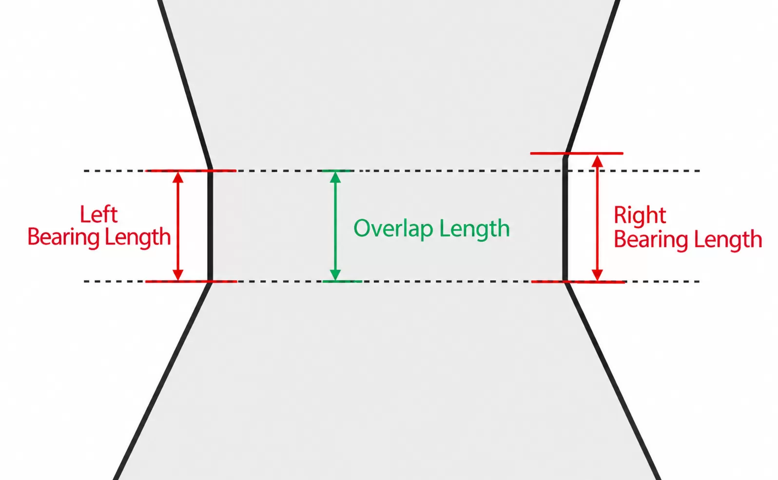
The effective bearing length is calculated using the following formula:
Effective Bearing Length = (Overlap of the Left and Right Bearing Zones + (Left Bearing Length + Right Bearing Length) / 2) / 2
This value is designed to represent the actual effective bearing length of the wire drawing die as accurately as possible.
Used together with 2D Die Aperture Gauge(DM Series) to build a complete measurement solution
Provides end-to-end support from product selection to production line operation through on-site guidance and after-sales technical support.